Avionics Enclosure Assembly
- 3D Parts Required:
- Avionics Enclosure Pi (bottom)
- Avionics Enclosure RFD/Air (top)
- Avionics Enclosure Plate (centre)
- Avionics Enclosure Front Mount
- Avionics Enclosure Rear Mount
- Avionics Enclosure Screw Washers
- Pi Camera Servo Mount
- Pi Camera Holder
- Components Required
- Airspeed Sensor
- I2C Bus
- FrSKy XSR RC Receiver
- RFD900x Radio Modem
- GPS M8N
- Pi Zero W
- Pi Camera Module v2
- Pi USB Hub Zero4U
- Pi Reboot Relay
- 1x Servo DS-929
- Pixhawk
- M4 Countersunk Screws 1x20mm and 1x28mm long
- M3 Countersunk Screws 4x10mm and 4x18mm long
Step 1 - Pre-Assembling the Avionics Enclosure
Tip
Not all 3D parts come off the printer in perfect condition. Before assembling or glueing any 3D printed parts, ensure that the parts all fit together by carefully removing any excess plastic from the print and seeing if they dry fit together first!
As always, it’s a good idea to make sure the 3D printed parts fit first without any components installed.
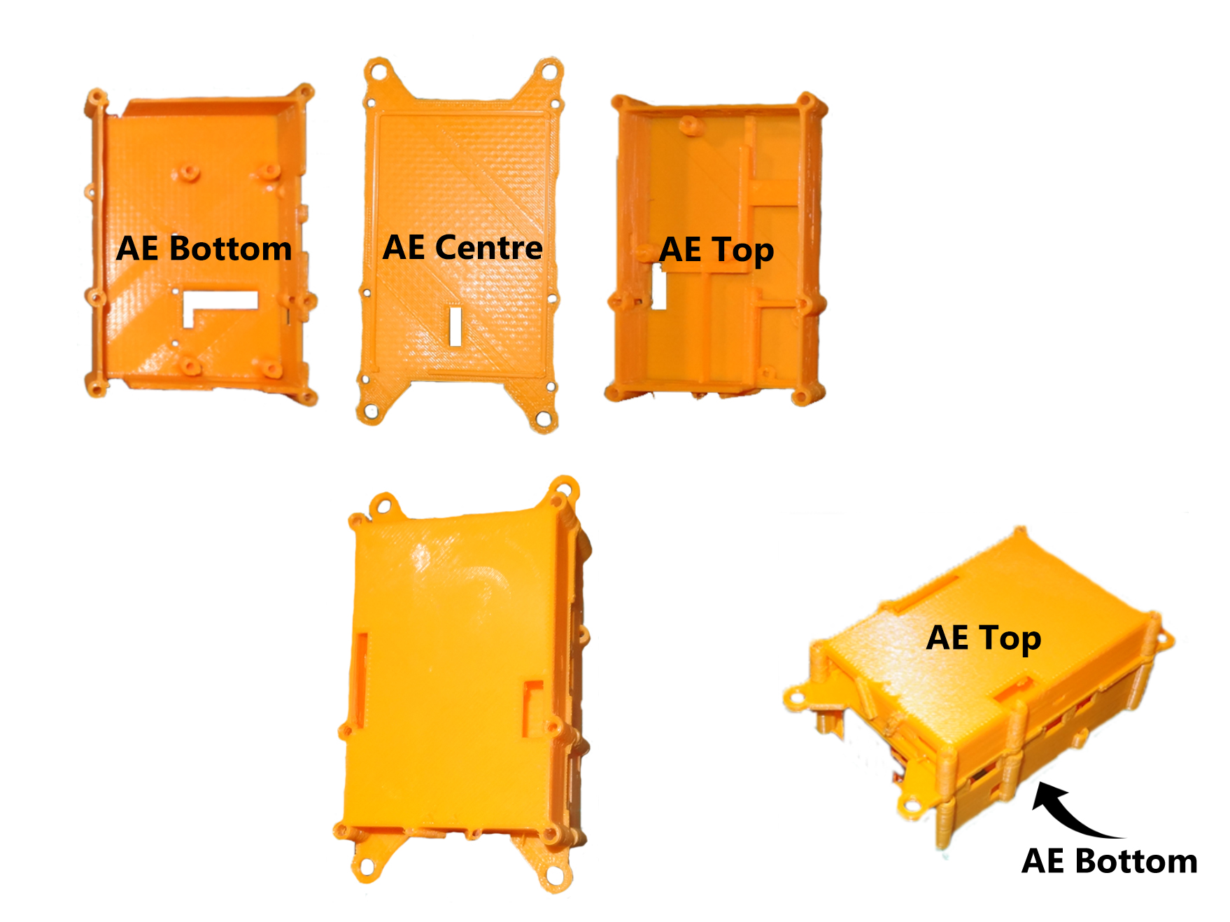
Assemble the Avionics Enclosure (AE for short) Pi, RFD/Air and Centre plate as follows, taking care to align the plastic and making the parts fit together seamlessly.
Step 2 - Assembling the Pi Avionics Enclosure
Carefully pull out the black plastic locking mechanism 1mm on the Pi Camera connector and insert the Pi Camera ribbon cable to the Pi Camera, with the contacts of the ribbon cable facing the Pi Camera PCB. Then, lock the ribbon cable in place by sliding the black plastic back in whilst the ribbon cable is fully inserted. Make sure the slot for the Pi Camera ribbon cable in the Pi Camera Servo Mount 3D print is clear and carefully test that the ribbon cable can be inserted through the slot.
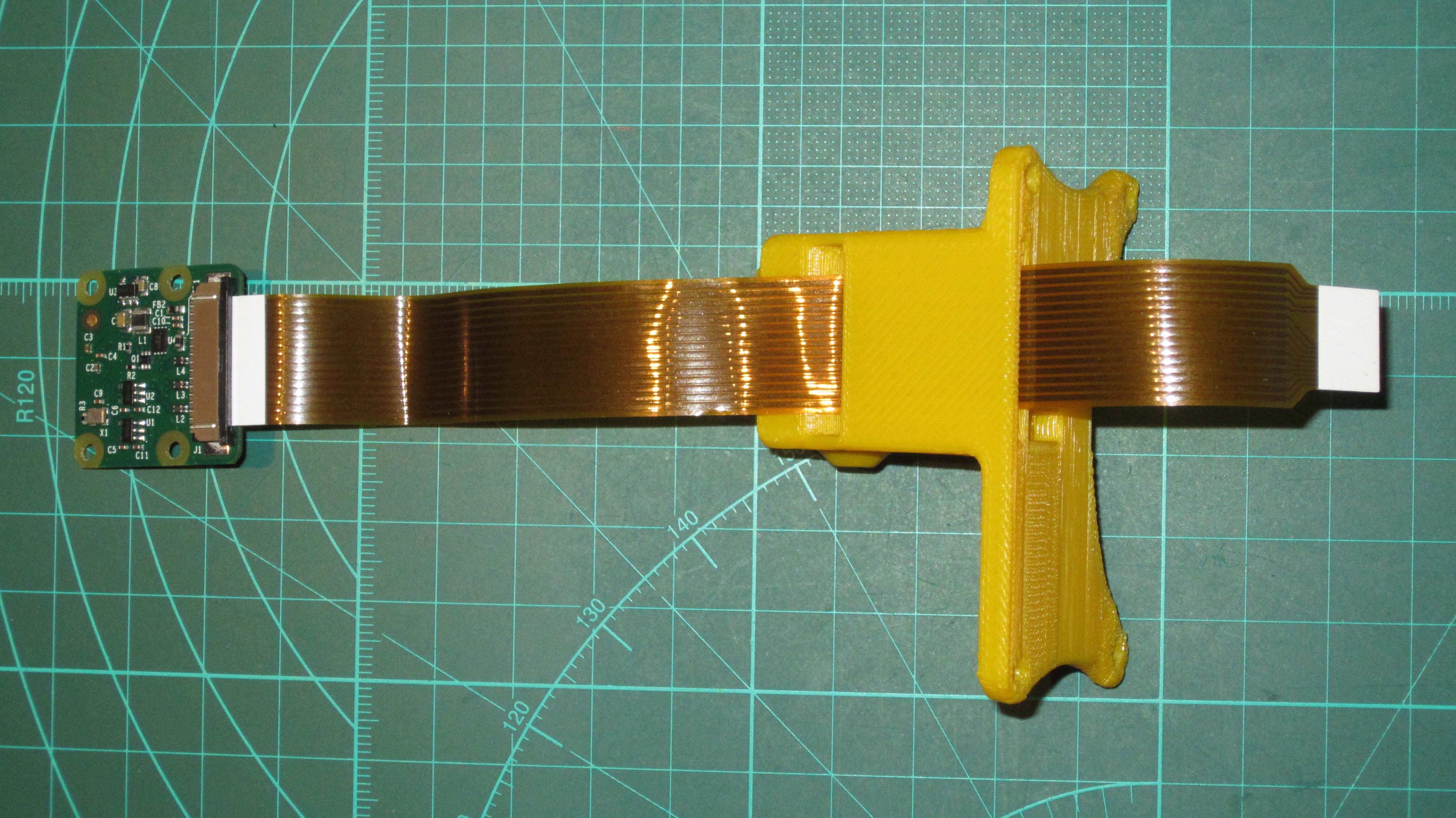
Then ensure the slot on the Pi Camera Servo Mount is clear and insert the Pi Camera ribbon cable in the orientation as shown. (Note: this must be the correct way otherwise it will not connect to the Pi Zero connector properly)
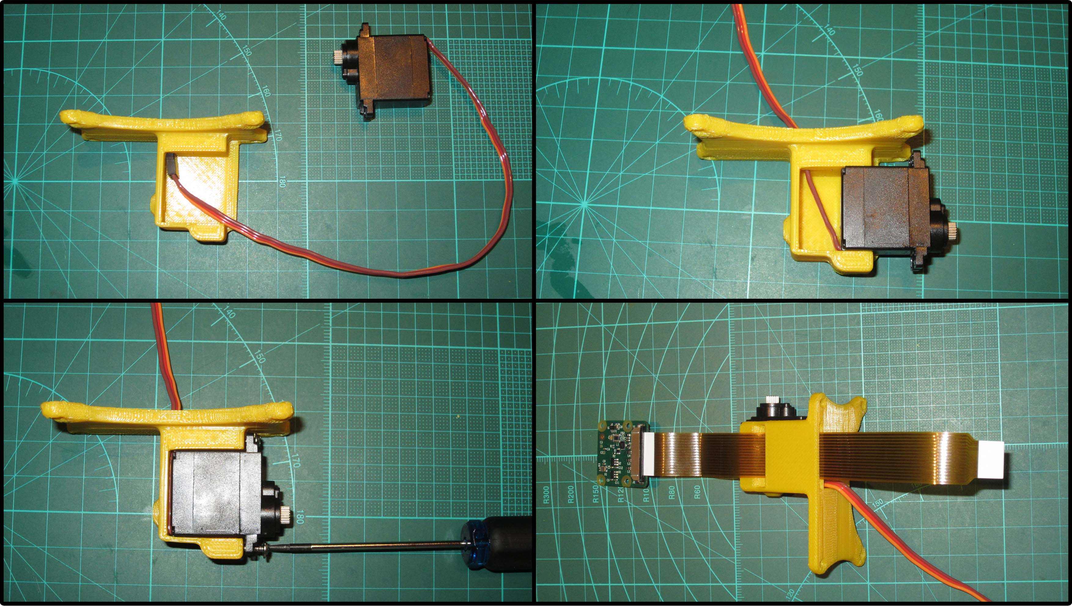
Insert the Servo plug into the Camera Servo Mount as shown, making sure there are no twists in the cable so the Servo fits seamlessly into the mount. Screw the servo to the mount using the screws provided with the servo.

Insert the cables through the Pi AE as shown, attach the Camera Servo Mount to the Pi Avionics Enclosure using the M3 10mm screws, and route the cables internally as shown above.
Note
The servo cable should be flat and routed in between the Pi Enclosure 3D printed screw risers and then towards the rear of the enclosure to the Pi Zero ribbon connector.
Tip
Use an M2.5 12mm metal screw to thread the 3D printed extrusions prior to using plastic screws to attach the Pi to the enclosure.
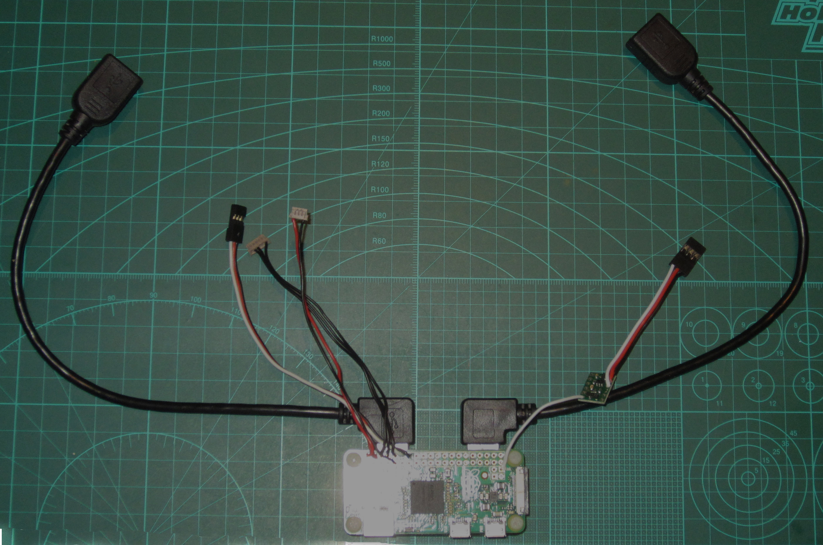
Take the completed Pi and USB assembly constructed Pi Setup phase, place it into the Pi AE and attach it with the USB HUB supplied plastic or equivalent metal screws. Route the cables as shown.
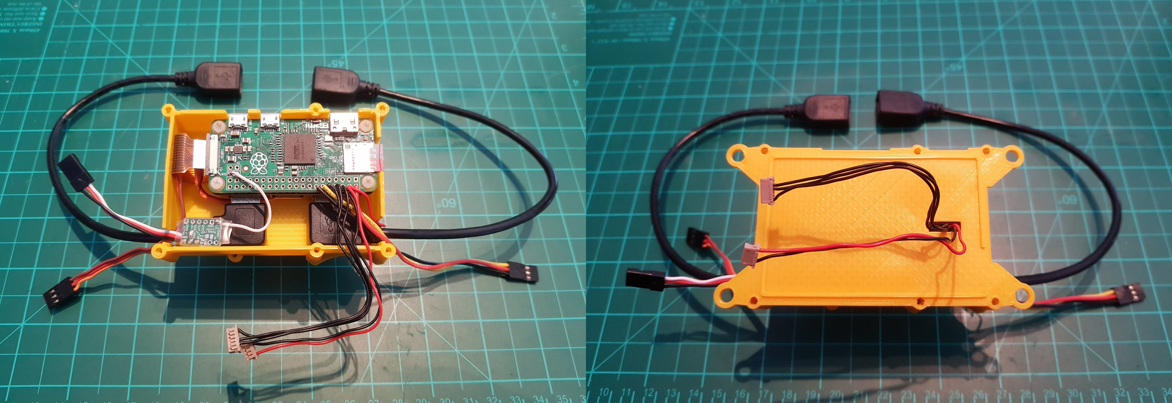
Route the two DF13 Cables as shown through the Centre Plate and place the Centre plate on Pi AE.
Step 3 - Assembling the Air/RFD Avionics Enclosure
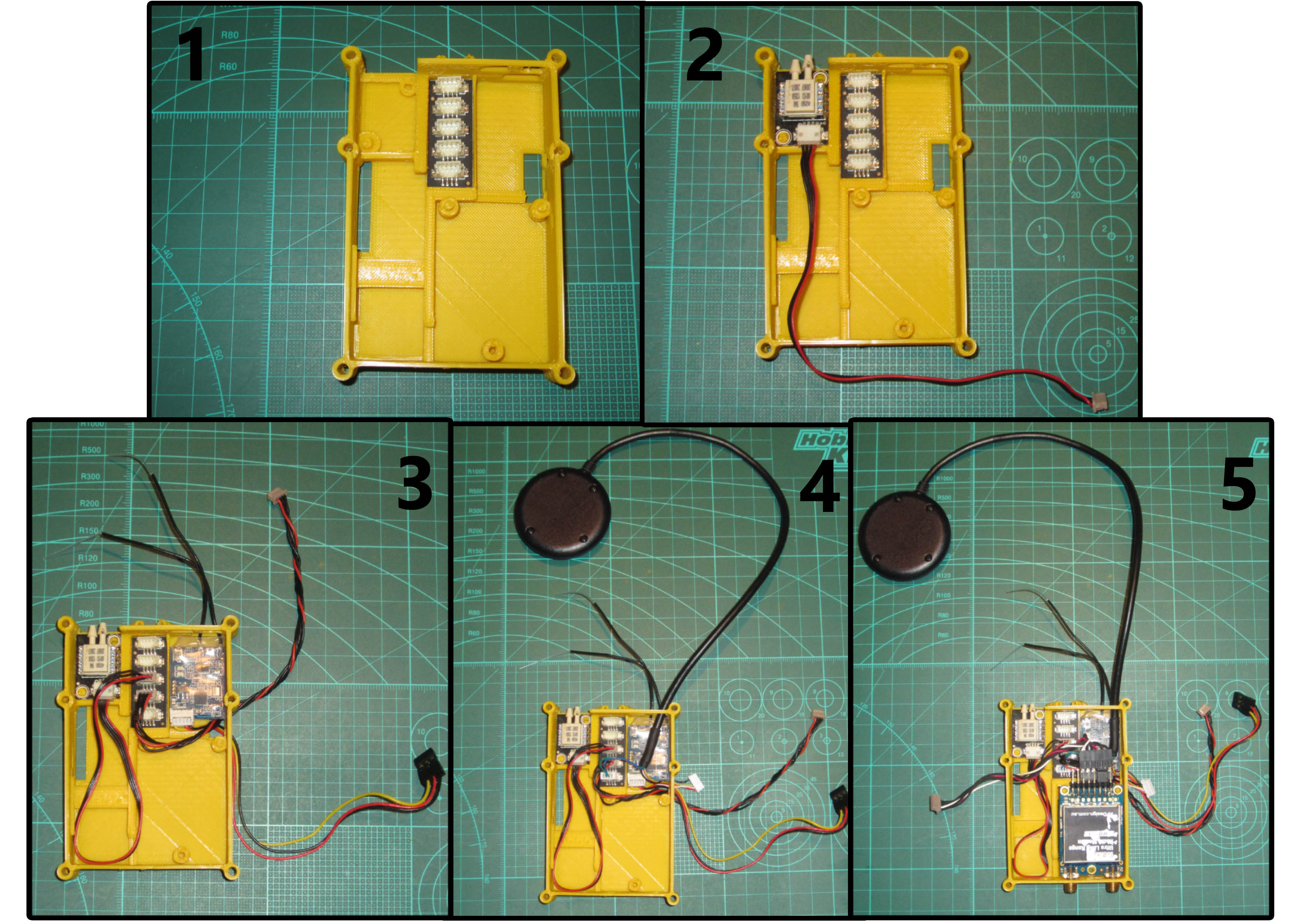
Insert I2C Hub into Air AE, then the Airspeed Sensor and XSR RC receiver (if used) with the binding button facing upwards as shown. Attach and route the two I2C cables, one between the Airspeed and I2C bus, and one I2C cable to the outside of the enclosure via the opening under the XSR receiver. Route the XSR servo connector out through the opening under the XSR.
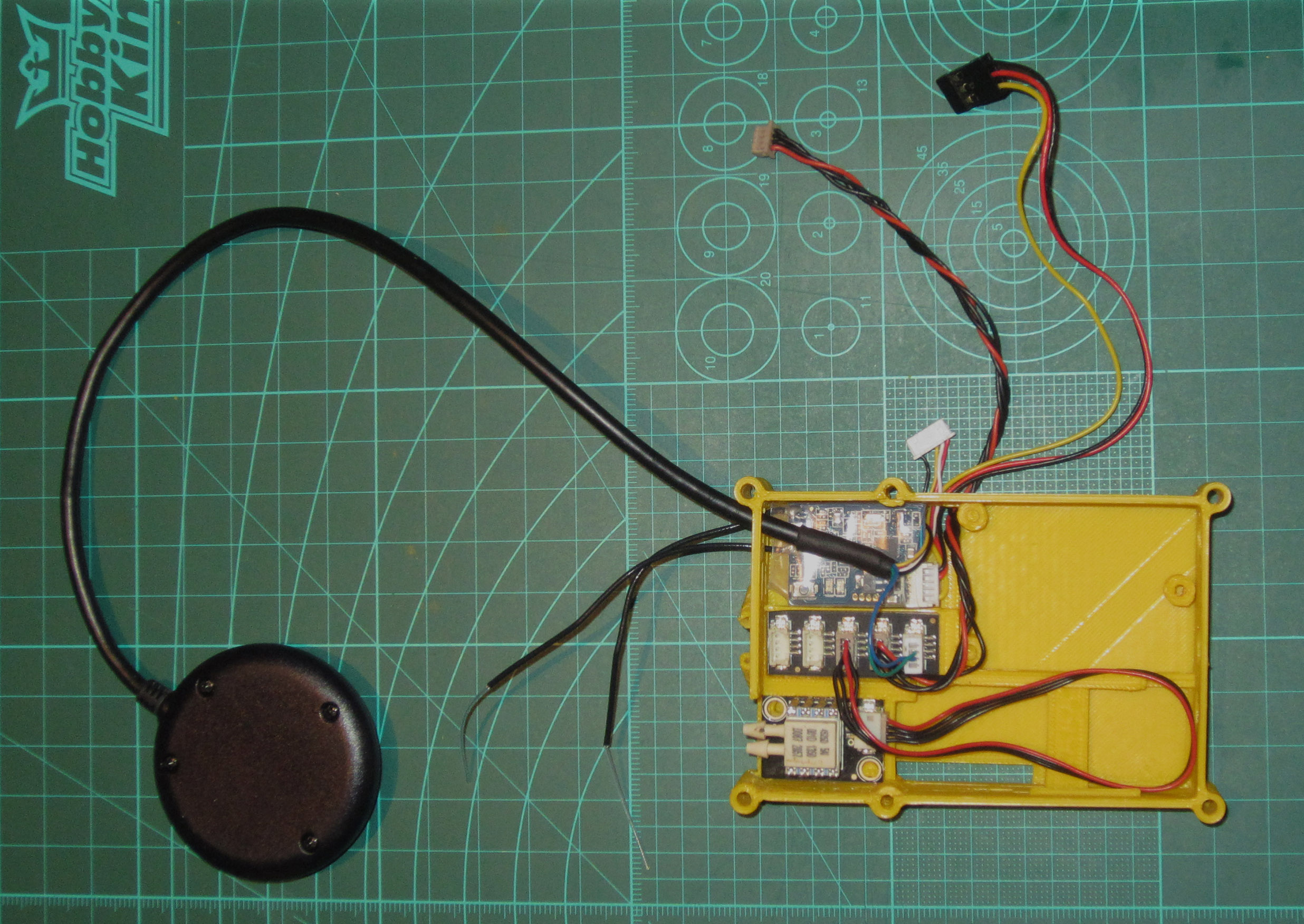
Next, insert the connectors of the GPS module on an angle through the top left opening of the Air AE, the GPS 4pin Connector plugs into the I2C hub and the 6 pin connector is routed out through the opening underneath the XSR.
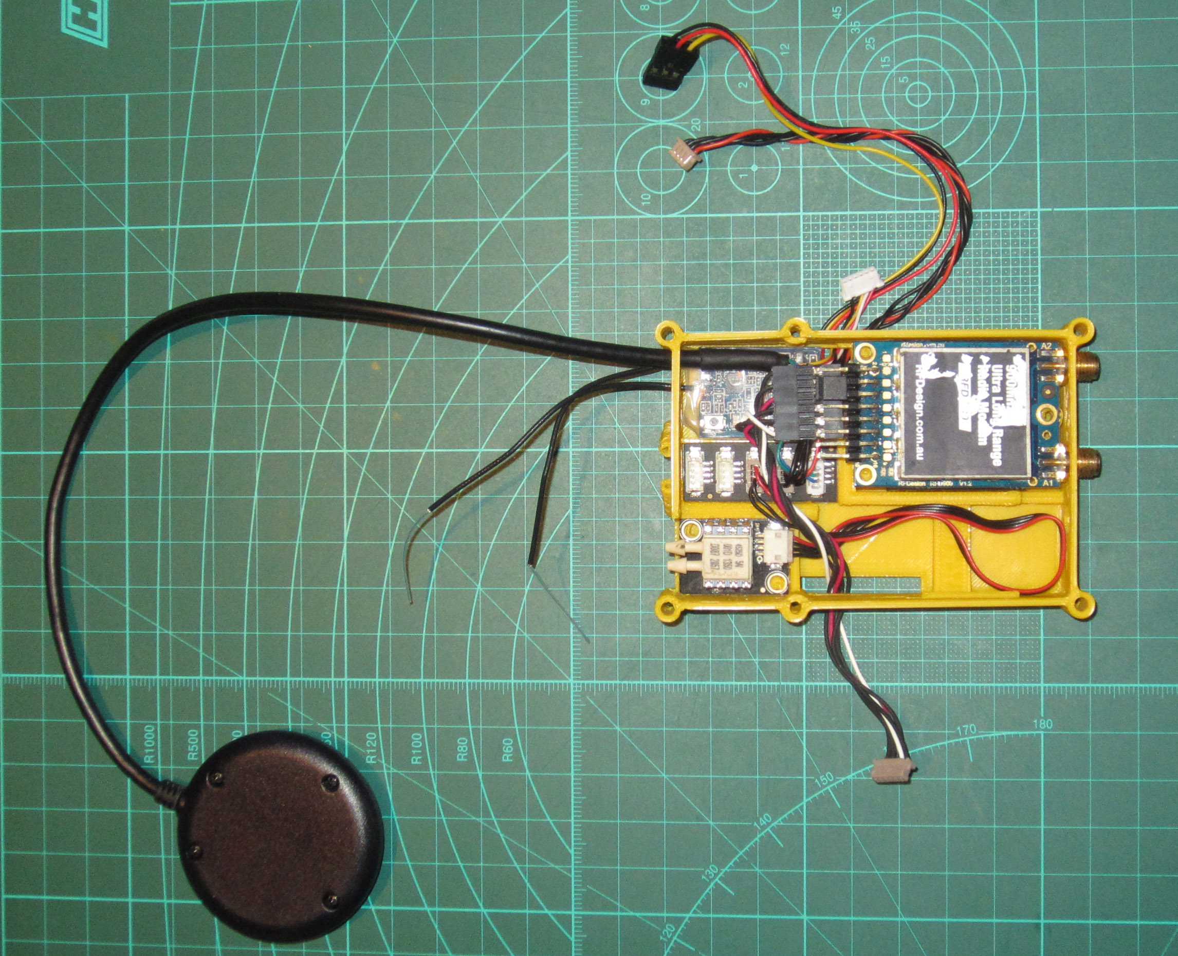
The RFD900 module cable can then be routed through the Airspeed sensor side opening, and can be placed with the antenna plugs through the enclosure and clipped into place. (The extra space in the Air/RFD AE can also be used to connect a secondary 3DR modem if required. For example for 433MHz)
Note
Make sure that various cables are routed correctly, and are not taut, or caught between components.
Step 4 - Assembly of the Enclosure
Route the two DF13 cables from the PiAE enclosure through the opening of the Air AE next to the Airspeed Sensor and back to the outside of the enclosure. These will need to be plugged into the Pixhawk later.
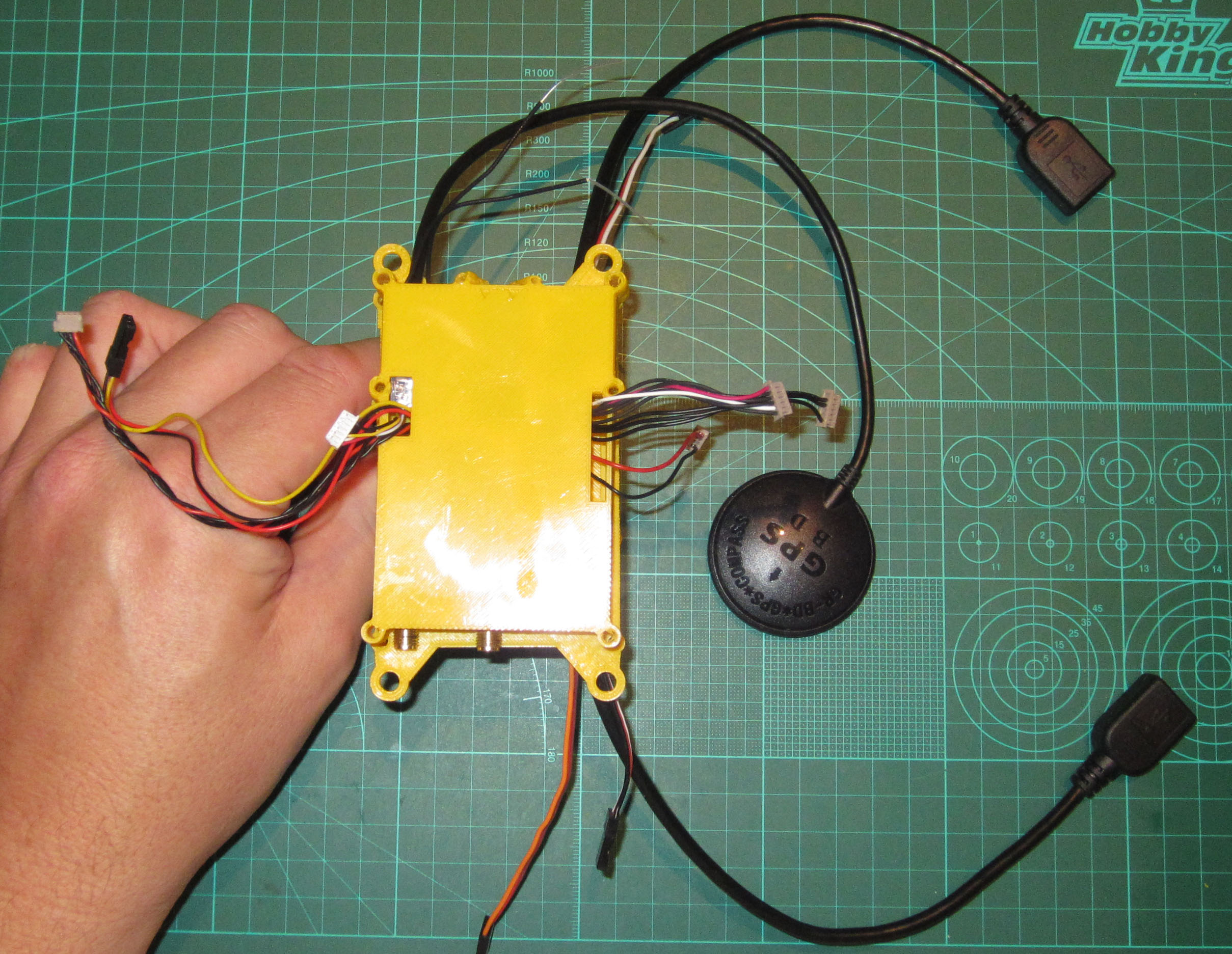
Carefully place the Air AE over the Centre Plate, making sure that the cables are clear of the contact areas and are long enough to reach their respective PXH connectors. You can use two screws to hold the enclosure together while you organize the PXH connectors and check cable lengths.
Tip
Some cables might be longer than necessary so, if required, the extra length can be contained in the enclosure to make the cable management neater.
Step 5 - Attaching and Connecting the Pixhawk
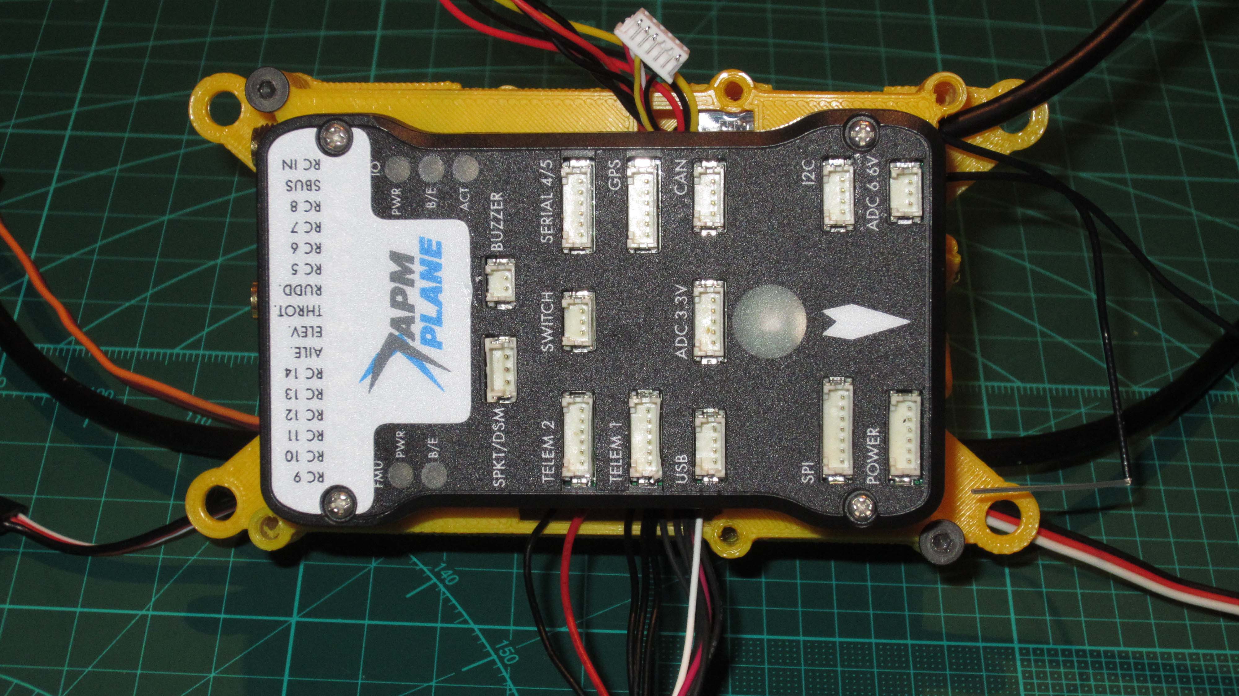
The Pixhawk can now be mounted, using double sided foam tape, on the top of the Avionics Enclosure with Servo rail of the Pixhawk facing the same side as the RFD antennas.
Tip
Try to align the PXH straight onto the enclosure before sticking it in place.
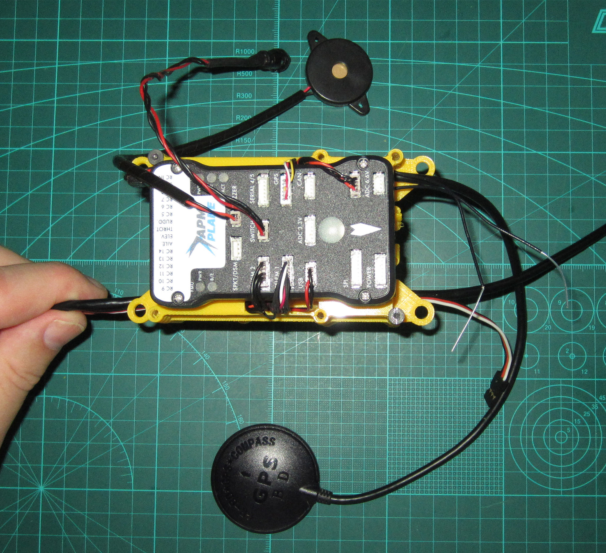
The cables can now be connected to the Pixhawk as follows:
- On the left side of the Pixhawk:
- RFD cable to Telem 1
- Pi Serial to Telem 2
- Power from Pi to USB (This is the third redundant power supply)
- On the right side of the Pixhawk:
- GPS cable to GPS
- I2C bus cable to I2C
- And in the middle:
- The Switch to the Switch and
- The speaker/Buzzer to the Buzzer
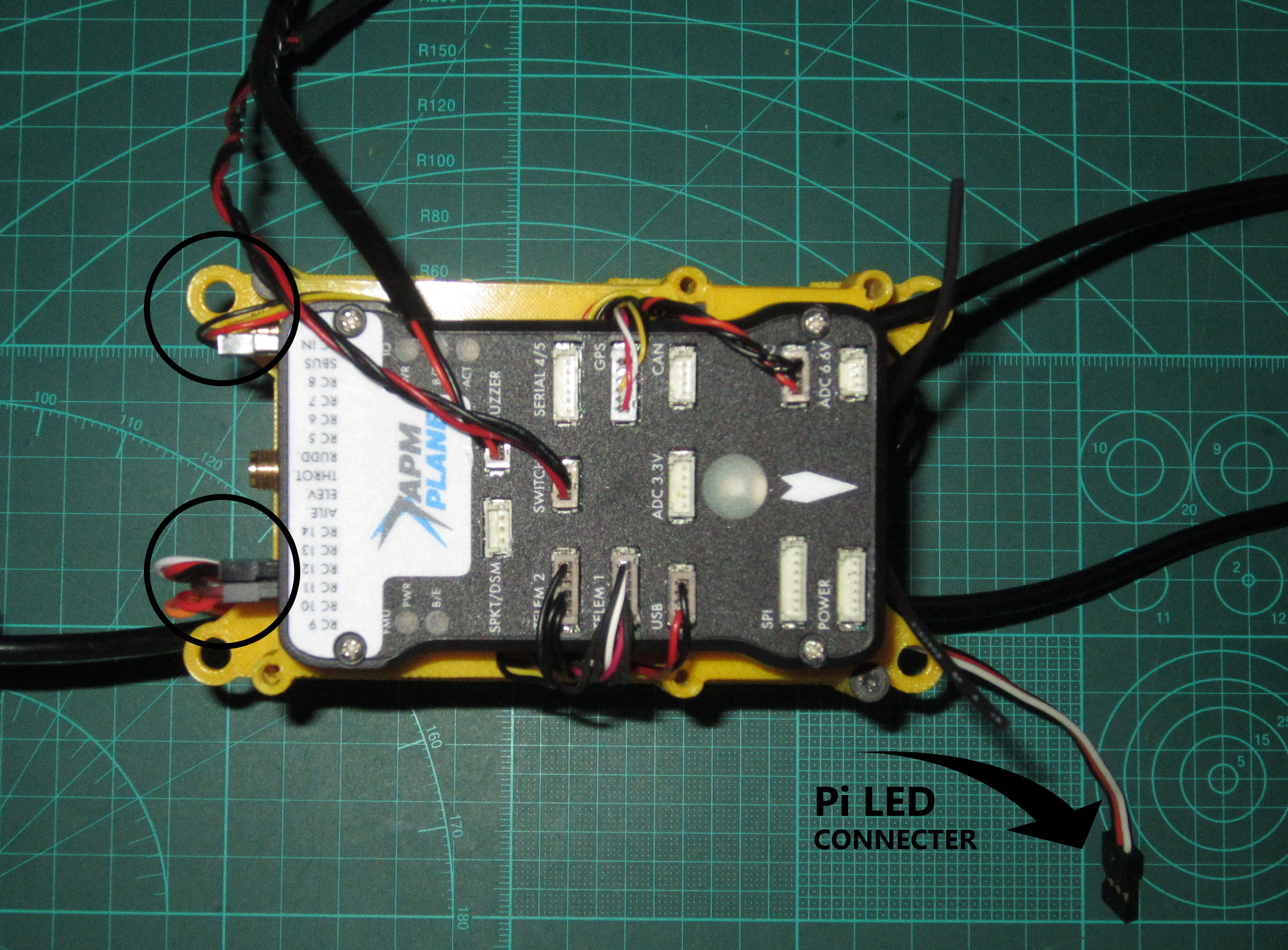
- And then, finally insert:
- the XSR Servo connector into RC IN
- the Camera Servo Connector into RC 11 (Aux 3)
- the Pi Reset Relay Servo connector into RC 12 (AUX 4)
The last thing to do is route the XSR Antennas through the top opening and through the Antenna holder tubes. (Heat shrink the antenna cables once attached to the enclosure to strengthen the frail cables against damage)
Caution
The Front Pi LED servo connector that comes from the Pi Zero header should never be inserted into the Pixhawk or any standard servo connector, as it is not compatible and can only be used with the LED strip as specified. Do not use this connector for anything else otherwise the Pi IO might become damaged.
Step 6 - Installing the Avionics into the Fuselage
Insert the M4 locking nuts into the recess provided in the 3D printed Front and Rear Mounts. The locking nuts can also be glued in if they are loose in the 3D Print; just keep the nut thread clear of glue. Install the damping balls on the Avionics Enclosure into the four large holes of the 3D printed Base plate. Then insert the other side of the balls into the 3D printed Front and Rear AE mount. The Front mount is higher than the Rear mount.
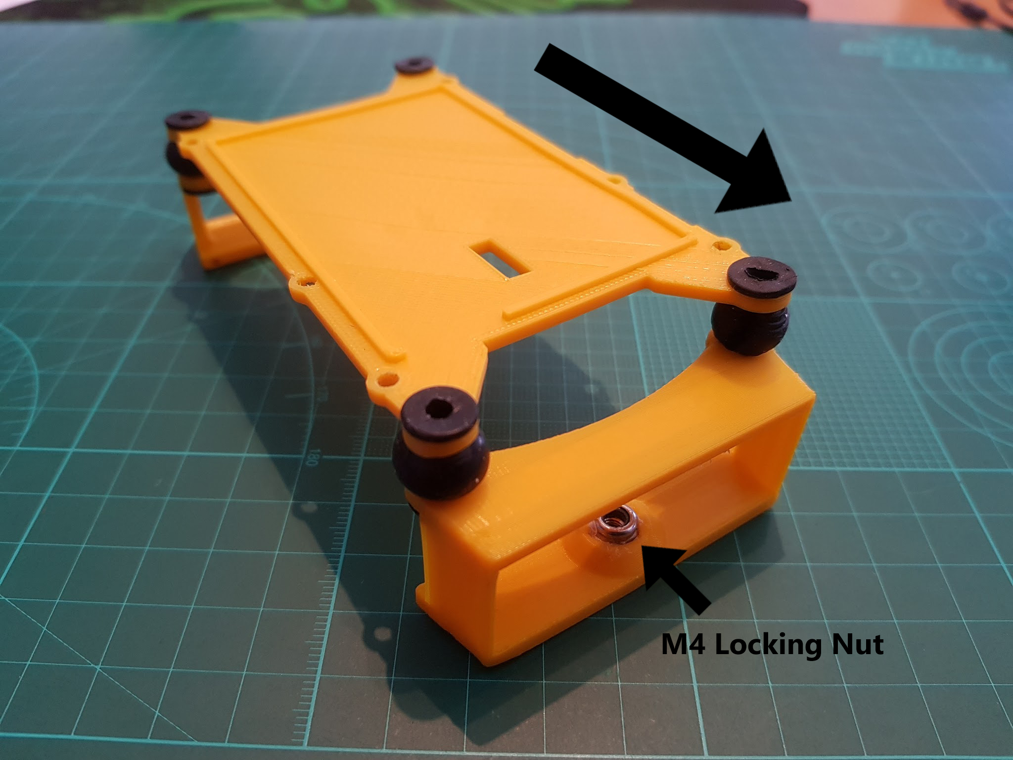
*Picture for damping ball setup illustration only.
Tip
To mount the rubber balls into the mounts and enclosure centre plate, insert them on one side first then carefully pull the rubber ring through the hole until the rubber is flush all the way around the hole.
Note
The front of the Avionics Enclosure is the direction the arrow should be pointing on the Pixhawk. The RFD antenna SMA connectors are on the rear of the enclosure.
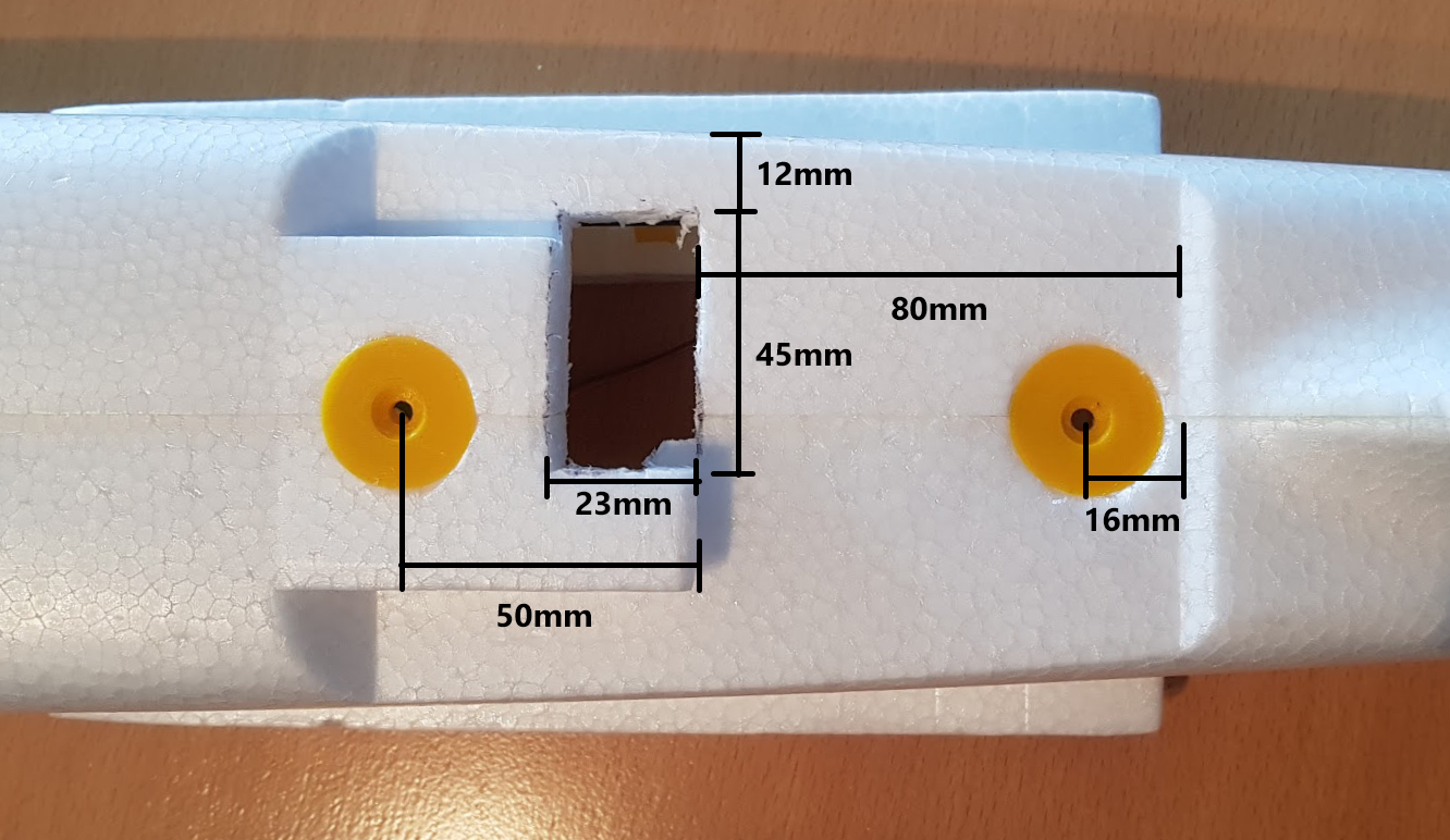
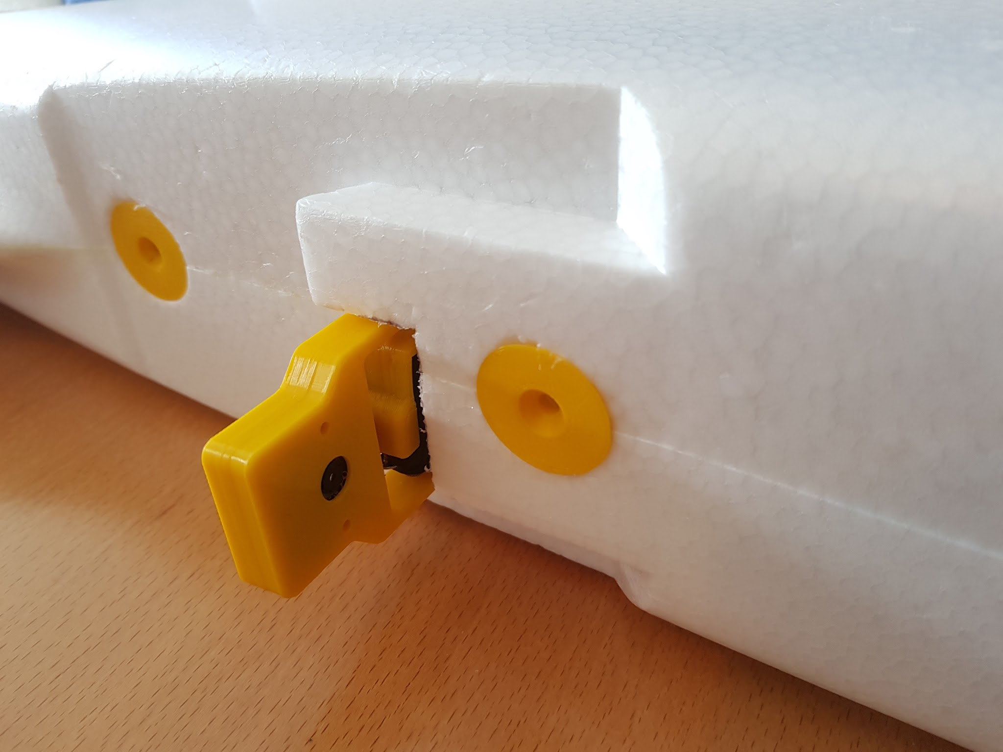
Use the 3D printed AE Screw Washers to mark the a circle where the foam needs to be recessed, according to the dimensions on the photo above, and in the middle of the fuselage foam seam. Use a hobby knife to only recess a cone shape for the washers into the foam so that they fit flush to the outside. Do not cut all the way through the fuselage foam! Then, hot glue the 3D printed Screw Washers in place, making sure they are straight and flush with the underside of the fuselage.
Mark the cutout for the camera gimbal as shown on the photo above. Try to keep the dimensions of the cutout as close as possible and only about 2-3mm larger than the Camera gimbal itself.
Tip
Once the AE is installed, the camera gimbal should be able to freely move inside the foam cutout, so that it is only attached by the enclosures damping ball system and does not touch anywhere else. This should then provide the camera with enough vibration damping in flight.
Carefully position the gimbal so that the camera is facing forwards and inline with the gimbal Servo so that it fits through the foam cutout in the fuselage.
Slowly and carefully insert the Avionics Enclosure into the fuselage, and guide the camera gimbal out through the bottom of the fuselage at the same time. Carefully use the M4 20mm screw to attach the Rear Mount and the 28mm screw to attach the front mount to the fuselage, whilst ensuring the camera gimbal is free to move in the foam cutout, and the Avionics Enclosure is aligned in the fuselage.
Finally, tighten the screws so the mounts cannot rotate and they partially compress the foam.
